Post-layout Simulation with Real Wire Delay
Like a below figure, you execute "Add Sources..." at "Simlation Sources", "Sim_1" in "Source" window.
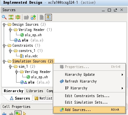
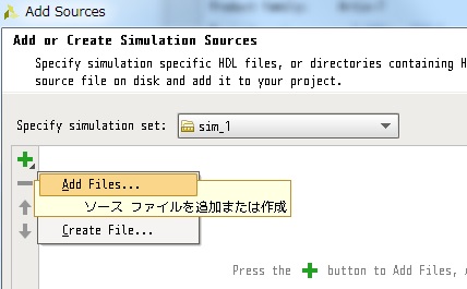
In next window, push "+" icon and select "Add Files...".
Select test bench files "add_test.v" and "add_test.vh", then push "OK".
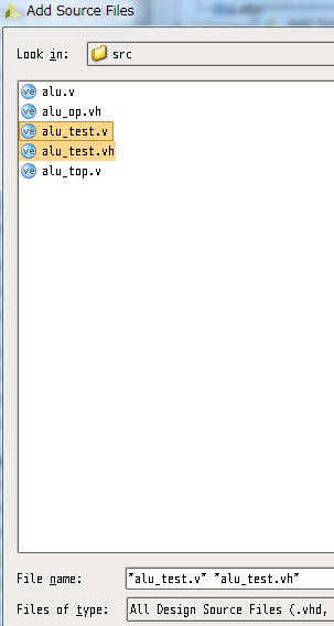
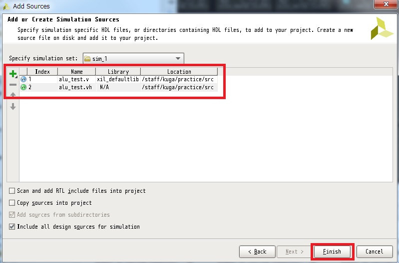
Next, push "Finish" in next window after checking the file order,
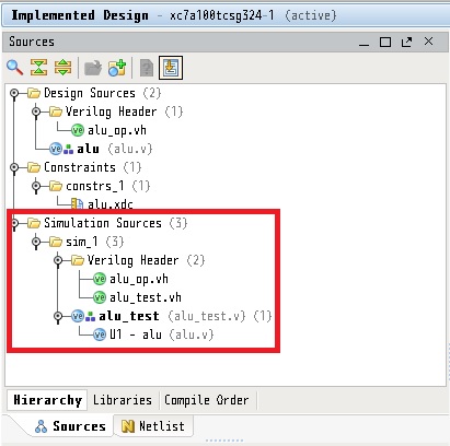
"alu_test.v" and "alu_test.vh".
After including testbench files, "Sources" window indicates file lists
like a below figure.
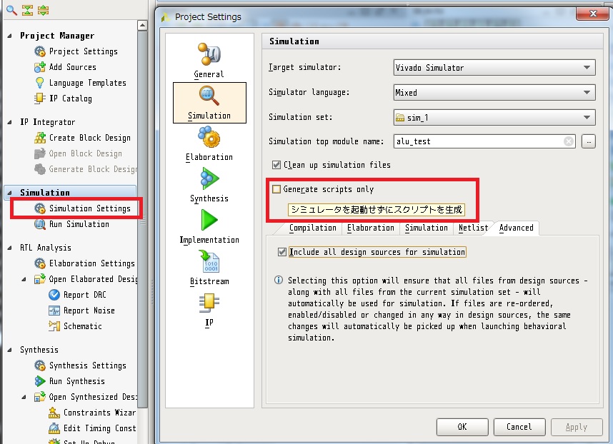
Next, you click "Simulation Settings" for checking simulation option.
You must uncheck the "Generate scripts only" option, and push "OK".
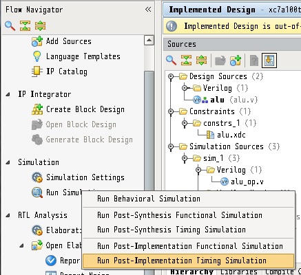
After that, you click "Run Simulation" and "Run Post-Implementation
Timing Simulation" to execute XSIM simulator.
To display all waveform, push "Zoom Fit" icon.
You can obtain a waveform result of the post-layout simulation similar to the functional simulation.
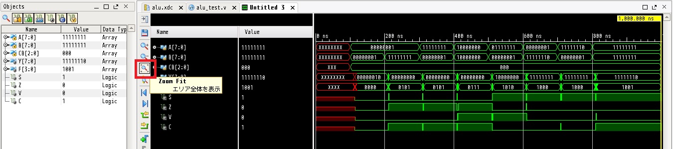
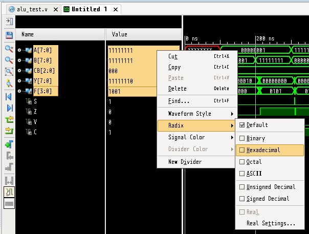
And then, change radix of signal value to hexadecimal number to readability.
We compare functional simlation result and post-layout simulation result.
Upper figure is post-layout simulation result with wire delay.
Lower figure is functional simulation result without wire delay.
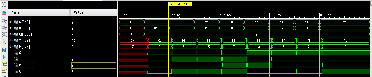
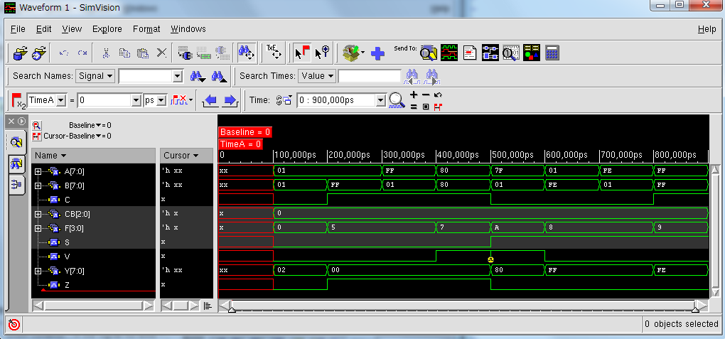
A wave changes from "01+01=02" to "01+FF=00" in a calculation of addition at near 200ns.
In the functional simulation, the result is got immediately.
But in the post-layout simulation, you can see that the result is got after wire delay.
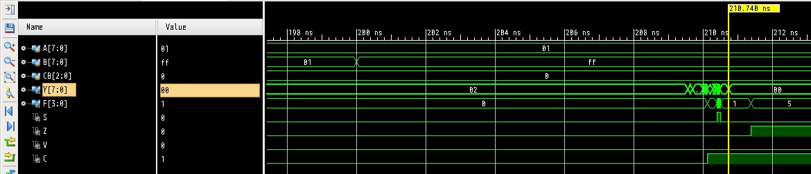
Zoom in at near 200ns for the wave changes.
The below figure shows that output "Y" is fixed after 10.740ns from input values are changed at 200.0ns.
And also, "C" flag has 10.109ns delay, "Z" flag has 11.366ns delay.
Now, we finished post-layot simulation.
Push "Close" button  to stop the
simulation and to close the window.
to stop the
simulation and to close the window.
Finally, we check the circuit behavior for validation.
|Home|