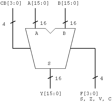

The flag output is a 4-bit bus and there are sign flag "S",
zero flag "Z", overflow flag "V", carry flag "C" in it.
The bit order of FR is FR[3:0] = { S, Z, V, C }.
Let's describe the ALU part in Verilog HDL as "alu.v".
Incidentally, be careful of working in the same directory from the design of ALU to functional simulation. .
module alu (A, B, CB, Y, F) ;
  input  [15:0] A ;
  input  [15:0] B ;
  input  [ 3:0] CB ;
  output [15:0] Y ;
  output [ 3:0] F ;

  reg    [16:0] tmp ;      // result
  reg    V ;               // for overflow

  always @ (A or B or CB)
  begin
    case (CB)
    `IADD     : tmp<= { 1'b0, A } + { 1'b0, B }; // Addition
       ...
       ...
       ...
       ...
       ...
       ...
       ...
       ...
       ...
    `ILSR   : tmp <= { A[0],  1'b0, A[15:1] };	// Logical right shift
       ...
       ...
       ...
       ...
    default : tmp <= { 1'b0, A }; 		// pass through operand A
    endcase
  end

  assign Y    =  reassigning result;

  always @( A or B or tmp or CB )
    case ( CB )
    `IADD   : V <= ( ( condition ) && (  condition ) ) ? 1 : 0;
    `ISUB   : V <= ( ( condition ) && (  condition ) ) ? 1 : 0;
    `IINC   : V <= ( ( condition ) && (  condition ) ) ? 1 : 0;
    `IDEC   : V <= ( ( condition ) && (  condition ) ) ? 1 : 0;
    `IASL   : V <= ( A[15] != tmp[15] ) ? 1 : 0;
    default : V <= 0;
  endcase

  assign F[3] = ...... ;	// Sign flag
  assign F[2] = ...... ;	// Zero flag
  assign F[1] = V;		// Overflow flag
  assign F[0] = ...... ;	// Carry flag

endmodule
Next, description of flag attempts to have.