Preparing of the DVI encoder module
DVI encoder module is needed for digital video interface.
In DVI, 8-bit RGB or total 24-bit pixel data every 25MHz must be output as high-speed serial communication.
In this experiment, we uses "dvi_out_native module" which is provided
as the reference design of ATLYS board.
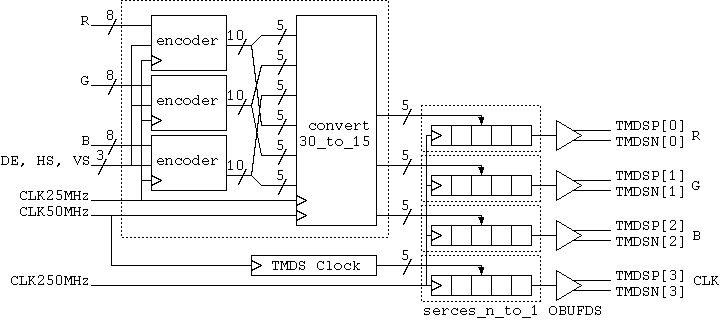
The following figure shows the "dvi_out_native module" structure.
The behavior is as the following.
- It encodes the parallel signal of 8 bits for each of RBG to 10 bits according to the rule of the DVI signal by the encoder module.
- It makes a 30-bit signal. First, 15 bits for each of RGB with 5 bits of the
higher rank, another 15 bits for each of RGB with 5 bits of lower rank.
- It sends a 30-bit signal every 15 bits at twice of frequencies by the convert_30_to_15 module.
- It changes 5 bits for each of RGB with the parallel-serial at 10 times of frequencies by the serdes_n_to_1 module and it sends them.
- It outputs as the differential-signal of LVDS with the OBUFDS primitive.
- It creates a clock for DVI separately and it outputs it with the serial signal of RGB.
The related archived file of dvi_out_native gets from here.
Extract the files by "tar zxvf dviout.tgz" command.
These files copy to the working directory.
The reference book
Urushidani: "Chapter 5 Bus/interface standard for image input and
display," Interface, pp.76-84, CQ Pub., Sep. 2009.
|Back|