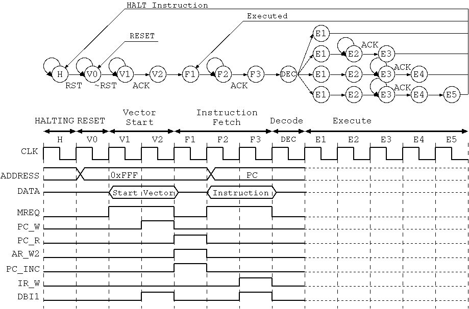

Since State (E1), the condition which the direction can take is different. In what is described as follows, the condition can be treated by the character string.
//
// State
//
'define HALTING      8'b00000000    // HALT
'define V0           8'b00000001    // RESET
'define V1           8'b00000011    // Vector Start
'define V2           8'b00000111
'define F1           8'b00001111    // Instruction Fetch
'define F2           8'b00001110
'define F3           8'b00001100
'define DEC          8'b00001000    // Decode

'define LDD_1        8'b00010000    // Load Direct
'define LDD_2        8'b00010001
'define LDD_3        8'b00010011

'define STD_1        8'b00010111    // Store Direct
'define STD_2        8'b00011111
'define STD_3        8'b00011110
'define STD_4        8'b00011100

'define CALL_1       8'b00100000    // Call
'define CALL_2       8'b00100001
'define CALL_3       8'b00100011
'define CALL_4       8'b00100111
'define CALL_5       8'b00101111

'define JP_1         8'b00110000    // Jump and Branch
'define HALT_1       8'b00110001
'define NOP_1        8'b00110111

'define BIOP_IMM_1   8'b00111111    // Binary Operations (Immediate)

'define BIOP_IDX_1   8'b01000000    // Binary Operations (Indexed)
'define BIOP_IDX_2   8'b01000001
'define BIOP_IDX_3   8'b01000011

'define INC_DEC_MV   8'b01010000    // INC, DEC, MV (Register Indirect)
'define MONO_1       8'b01010111    // Unary Operations (Inherent)

'define LDI_1        8'b01100000    // Load Immediate

'define LDX_1        8'b01100001    // Load Indexed
'define LDX_2        8'b01100011
'define LDX_3        8'b01100010

'define STX_1        8'b01110000    // Store Indexed
'define STX_2        8'b01110001
'define STX_3        8'b01110011
'define STX_4        8'b01110111

'define IN_1         8'b10000000    // In
'define IN_2         8'b10000001
'define IN_3         8'b10000011

'define OUT_1        8'b10000111    // Out
'define OUT_2        8'b10001111
'define OUT_3        8'b10001110
'define OUT_4        8'b10001100

'define POP_1        8'b10010000    // Pop
'define POP_2        8'b10010001
'define POP_3        8'b10010011

'define PUSH_1       8'b10100000    // Push
'define PUSH_2       8'b10100001
'define PUSH_3       8'b10100011
'define PUSH_4       8'b10100111

'define RET_1        8'b10110000    // Ret
'define RET_2        8'b10110001
'define RET_3        8'b10110011
'define RET_4        8'b10110111
Next, it gives the definition of the command code. It is convenient because it is not 0 and 1 row and it is possible to handle the identifying of a direction as the character string when doing this description beforehand. A description example is shown below. It saves in the file name like "opcode.v" and it will should refer in include.
//
// Instruction Code
//
`define OP_4        IR [15:12]       // 4 bits OP code Field
'define IR_LDD      4'b0000
'define IR_STD      4'b0001
'define IR_CALL     4'b0010
'define IR_JP       4'b0011
'define IR_JPC      4'b0100
'define IR_JPZ      4'b0101
'define IR_JPS      4'b0110
'define IR_JPV      4'b0111

`define OP_6        IR [15:10]       // 6 bits OP code Field
'define IR_ADD      6'b100000
'define IR_SUB      6'b100001
'define IR_INC      6'b100010
'define IR_DEC      6'b100011
'define IR_OR       6'b100100
'define IR_EOR      6'b100101
'define IR_AND      6'b100110
'define IR_NOT      6'b100111
'define IR_LSL      6'b101000
'define IR_ASL      6'b101001
'define IR_LSR      6'b101010
'define IR_ASR      6'b101011
'define IR_ROL      6'b101100
'define IR_ROR      6'b101101
'define IR_SWP      6'b101111
'define IR_LD       6'b110000
'define IR_ST       6'b110001
'define IR_IN       6'b110010
'define IR_OUT      6'b110011
'define IR_POP      6'b110100
'define IR_PUSH     6'b110101
'define IR_RET      6'b111000
'define IR_MV       6'b111100
'define IR_HALT     6'b111110
'define IR_NOP      6'b111111

`define OP_M        IR [9:8]        // Addressing Mode Field
'define IMM         2'b01           //     Immediate
'define IDX         2'b10           //     Indexed

`define OP_A        IR [13:10]      // ALU Code Field

`define OP_D        IR [3:2]        // Destination Register Field
`define OP_S        IR [1:0]        // Source Register Field
'define RD_ACC      2'b00           // Register Code
'define RD_SP       2'b01
'define RD_IXR      2'b10
'define RD_PC       2'b11
Next, State's description attempts to have.