Post-layout Simulation with Real Wire Delay
Like a below figure, you execute "Generate Post-Place & Route
Simulation Model" at "Implement Design", "Place & Route" in "Process" window.
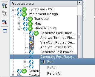
By this way, several files are generated for real wire delay simulation.
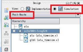
Next, you must change "Implementation" to "Simulation" at "View:" in "Hierarchy"
window, and also change "Behavioral" to "Post-Route" of selectable
menu.
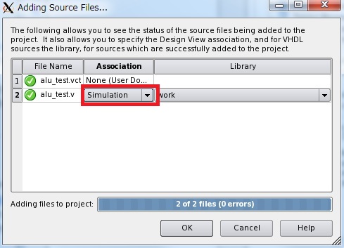
You must include the test bench file and test vector file same as
functional simulation.
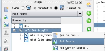
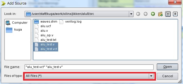
"alu_test.v" is used for simulation, so you change to "Simulation" in "Association" column.
Click "OK".
After file including, "Hierarcy" window indicates like a below figure.
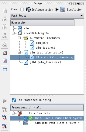
Next, you execute "Post-Place & Route Check Syntax" by double click of
mouse in "Process: alu_test" for checking syntax error.
After that, you execute "ISim" simulator of ISE suite by mouse double
click at "Simulate Post-Place & Route Model".
Simulator window indicates like a below figure after starting simulator.
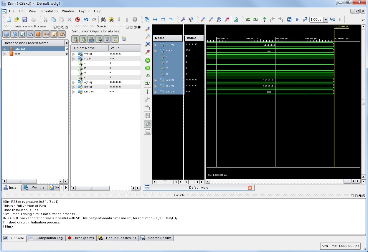
To display all wave form, you push 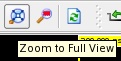 "Zoom to Full View" icon.
You can obtain a waveform in post-layout simulation similar to the functional simulation.
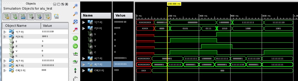
We compare functional simlation and post-layout simulation.
Upper figure is post-layout simulation result with wire delay.
Lower figure is functional simulation result without wire delay.
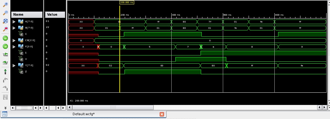

A wave changes from "01+01=02" to "01+FF=00" in a calculation of addition at near 200ns.
In the functional simulation, the result is got immediately.
But in the post-layout simulation, you can confirm that the resust is got after wire delay.
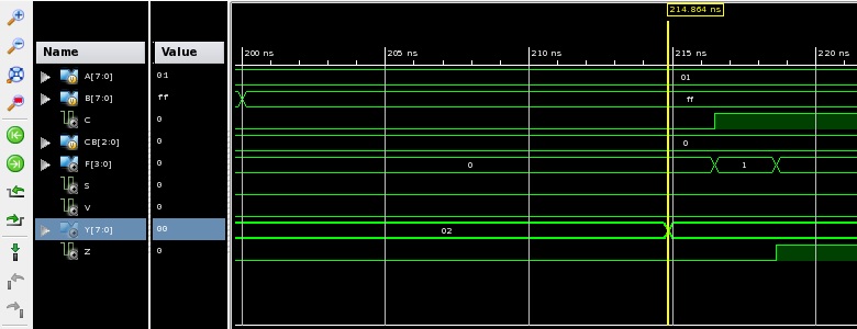
Zoom in at near 200ns for the wave changes.
The below figure shows that output "Y" is fixed after 14.864ns from input values are changed at 200.0ns.
And also, "C" flag has 16.486ns delay, "Z" flag has 18.607ns delay.
Now, we finished post-layot simulation.
Finally, we check the circuit behavior for
validation.
|CAD Home |