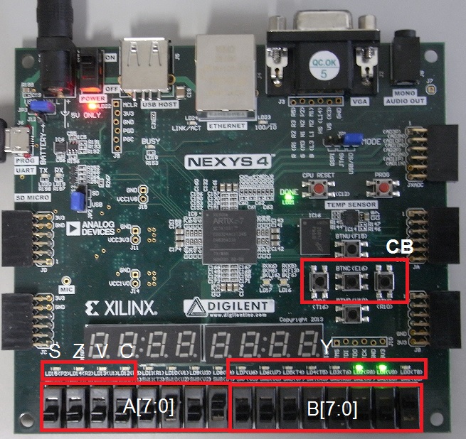
ATLYS has many switches and LEDs.
but we use limited switch and LEDs surrounded red boxes for validation of ALU.
Inputs and outputs of ALU are assigned to switches and LEDs namely white fonts.
Block diagram of ATLYS board for ALU circuit is shown in a below figure.
For example, high level is input to FPGA pin when toggle switch is turned on.
The result "Y[7:0]" is output on LEDs as binary value.
Next, let's try to execute.